ALL THESE ARE JUST BASICS YOU NEED TO THINK AND DO IT ON YOUR OWN DONT TRY TO JUST COPY IT DIRECTLY
A pick and place robot is the one which is used to pick up an object and place it in the desired location. It can be a cylindrical robot providing movement in horizontal, vertical and rotational axes, a spherical robot providing two rotational and one linear movement, an articulate robot or a scara robot (fixed robots with 3 vertical axes rotary arms).
Advantages
Before moving further, let us see few reasons why pick and place robots are preferred:
- They are faster and can get the work done in seconds compared to their human counterparts.
- They are flexible and have the appropriate design.
- They are accurate.
- They increase the safety of the working environment and actually never get tired.
Parts of a Pick N Place Robot
Let us see what the pick and place robot actually consists of:
- A Rover: It is the main body of the robot consisting of several rigid bodies like a cylinder or a sphere, joints and links. It is also known as a manipulator.
- End Effector: It is the body connected to the last joint of the rover which is used for the purpose of gripping or handling objects. It can be an analogy to the arm of a human being.
- Actuators: They are the drivers of the robot. It actually actuates the robot. It can be any motor like servo motor, stepper motor or pneumatic or hydraulic cylinders.
- Sensors: They are used to sense the internal as well as the external state to make sure the robot functions smoothly as a whole. Sensors involve touch sensors, IR sensor etc.
- Controller: It is used to control the actuators based on the sensor feedback and thus control the motion of each and every joint and eventually the movement of the end effector.
Working of a Basic Pick N Place Robot:
The basic function of a pick and place robot is done by its joints. Joints are analogous to human joints and are used to join the two consecutive rigid bodies in the robot. They can be rotary joint or linear joint. To add a joint to any link of a robot, we need to know about the degrees of freedom and degrees of movement for that body part. Degrees of freedom implement the linear and rotational movement of the body and Degrees of movement imply the number of axis the body can move.
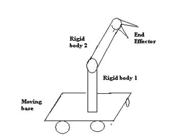
A simple pick and place robot consists of two rigid bodies on a moving base, connected together with rotary joint. A rotary joint is a one which provides rotation in 360 degrees around any one of the axes.
- The bottom or the base is attached with wheels which provide linear movement.
- The 1st rigid body is fixed and supports the second rigid body to which the end effector is provided.
- The 2nd rigid body is provided with movement in all 3 axes and has 3 degrees of freedom. It is connected to the 1st body with a rotational joint.
- The end effector should accommodate all 6 degrees of freedom, in order to reach all sides of the component, to take up position to any height.
On a whole, the basic pick and place robot works as follows:
- The wheels underneath the base help to move the robot to the desired location.
- The rigid body supporting the end effector bends or straightens up to reach the position where the object is placed.
- The end effector picks up the object with a strong grip and places it at the desired position.
Now that we have got a brief idea of the pick and place robot, the basic question is how it is actually controlled.
A simple pick and place robot can be controlled by controlling the movement of its end effector. The motion can be using hydraulic motion, i.e. using hydraulic fluid under pressure to the drive the robot, or using pneumatic motion, i.e. using pressurized air to cause mechanical motion. However the most effective way is using motors to provide the required motion. The motors have to be controlled in order to provide required motion to the robot and the end effector.
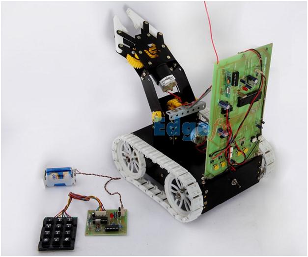
Working Example of Controlling a Pick N Place Robot
How about controlling the robot with a just a few buttons on the keypad? Yes, it is possible! Just pressing the required button, we can transmit command to the robot to make it move in any direction to achieve our task. Moreover this can be achieved using simple wireless communication.
Let’s see how this actually works:
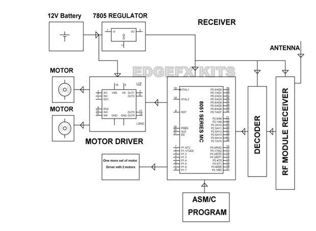
The transmitter part consists of the keypad interfaced to the microcontroller. Any button number in decimal format is converted to 4 digit binary by the microcontroller and the parallel output at one of its port is applied to the encoder. The encoder converts this parallel data to serial data and this is fed to the transmitter, fitted with an antenna to transmit the serial data.
![]()